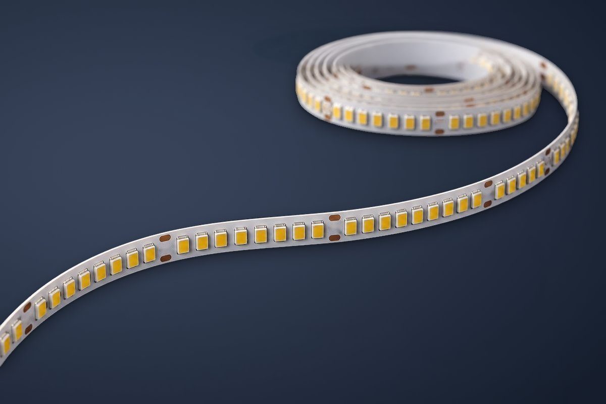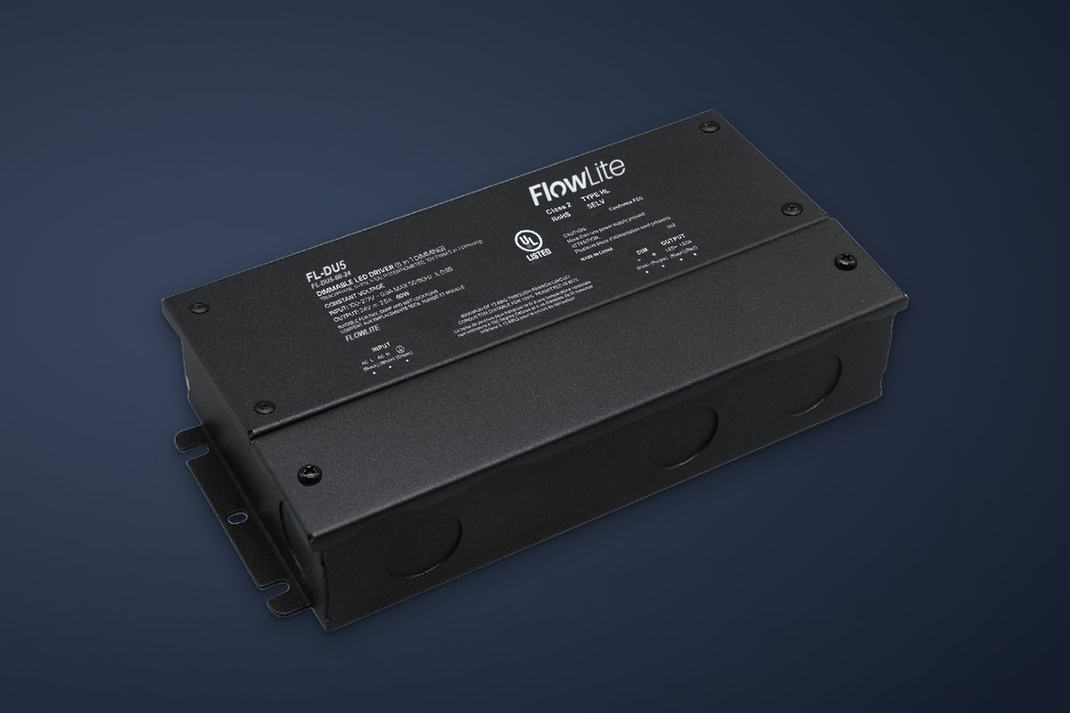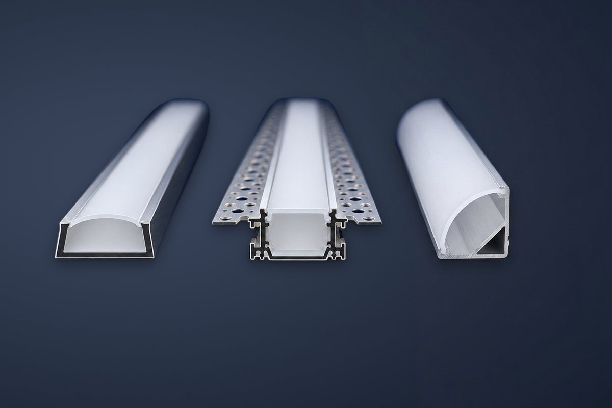
Most tape light problems that show up after handover were built in during installation: a feed point in the wrong place, a connector without strain relief, adhesive pressed onto a dusty surface. None of them are hard to avoid. This checklist covers what experienced installers do on every job.
Rough-in
- Confirm the layout. Check run lengths against the drawings and the tape's maximum run (16.4 ft for standard tape, 49.2 ft for long-run). Mark every feed point.
- Locate drivers. Place them in junction boxes or approved enclosures that stay accessible after finishes go in, as close to the runs as practical.
- Pull the right wire. Use copper conductors sized from the voltage drop chart, rated at least 176°F / 80°C. Label each home run at both ends.
- Leave service loops. A little extra cable at each feed makes final connections and future service far easier.
- Block for channels. Coordinate with millwork and drywall trades so channels have a straight, solid substrate.
Cutting
- Cut only on the marked cut lines (free-cut COB excepted). Cutting anywhere else leaves a dead segment.
- Use sharp scissors or snips and cut squarely through the center of the copper pads.
- Measure twice. Lay the tape in the channel dry before removing any adhesive liner.
Mounting
- Clean the surface. Wipe channels and substrates with isopropyl alcohol and let them dry. Dust, oil and drywall residue are the enemy of adhesive.
- Mount in a channel where you can. Aluminum channels manage heat, keep lines straight and protect the tape.
- Press, don't pull. Peel the 3M™ liner progressively and press firmly along the full length. Never stretch the tape to make it fit.
- Respect bend limits. Bend only along the flat plane and never crease the board. Don't bend at or near the LEDs or the solder joints.
- Mind the temperature. Install and operate within the tape's rated ambient range. Adhesive bonds poorly when the substrate is very cold.
Connecting
- Observe polarity. V+ to V+, V− to V−, every time. Reversed polarity on a segment means it simply won't light.
- Use the system's connectors. FlowLite tape-to-tape, tape-to-lead, jumper and splice connectors are made for each series' board width and pad layout. Soldering is fine when done by a skilled hand with heat-shrink over the joint.
- Relieve strain. Never let lead wires hang from a solder joint or connector. Secure cables with clips so the joint carries no load.
- Feed each run separately. Each maximum run needs its own feed. Don't extend beyond the maximum run length.
Testing and handover
Test before you close up
Power every run before lenses, trims or millwork panels go on. Check every segment, every joint and the far end of each run.
Check the voltage
Measure at the far end of long runs under load. If it is well below the driver's output, revisit wire size or feed location.
Check dimming
Run the dimmer through its full range and watch for flicker, dropout or uneven segments at low levels.
Document
Record driver locations, circuits and feed points on the as-builts, and leave the spec and installation sheets with the owner.
Key takeaways
- Plan feed points and driver locations before rough-in, and keep drivers accessible.
- Cut only on the marks, clean surfaces with isopropyl and mount in channel.
- Observe polarity, relieve strain and feed each run separately.
- Test every run and the dimming range before anything is closed up.