Every FlowLite tape, channel and driver has its own two-page installation sheet. They are all in Downloads, beside each product’s spec sheet. Example: FlowLine 4.4 installation sheet (PDF).
Before you start
- Always ensure the power supply connection to the electrical circuit is disconnected before working on it.
- Product to be installed and serviced by a qualified, licensed electrician, in accordance with local and national electrical code regulations.
- Do not connect 24V DC tape lights directly to 120V AC power. Use only with a Class 2 power supply, and make sure its voltage matches the tape (24V DC).
- Do not exceed the maximum run listed for the product (on its spec sheet, installation sheet and packaging). Each maximum run requires a dedicated power feed from the driver.
- Do not overload the 24V DC power supply: load it to no more than 80% of its rating. Overloading may cause shorting, overheating, and possibly fire.
- Do not power on the tape until the entire reel is unwound, and never cut it with power connected.
- Cut only at the designated cut points. Cutting anywhere else damages the tape.
- Do not install where the diodes are exposed to direct sunlight, or where the ambient temperature is outside the product’s listed range.
- Do not modify or disassemble the product beyond the instructions. Failure to follow safety warnings and installation instructions will void the warranty.
Handling the tape
- Do not bend LED tape light on a horizontal plane.
- Do not cover tape light with any materials.
- Do not bend LED tape light to a diameter less than 4".
- Do not fold, crease or twist LED tape light.
- When removing the backing and laying the tape to the surface, avoid ripples and bending over 90°.
- Avoid sharp bends, or bending within 1" of the solder joints.
- Do not power tape light while it is attached to the spool or tightly coiled.
Step by step
Measure and cut
Measure and cut the LED strip to the desired length: simply cut it with scissors along the marked cut point. The cut increment for each tape is on its spec sheet and installation sheet.
Connect
Solder the lead wire onto the solder pad, confirming the wires are matched correctly (+ to +, − to −; V+/CW/WW on tunable white; V+/R/G/B/WW/CW on RGB+Tunable White). Or insert the exposed contacts at the end of the strip into the connector and gently tighten the screw. Recommended soldering iron temperature: 600°–650°F for lead-free solder.
Clean the surface
Using a 50/50 alcohol mix, thoroughly clean the surface of the extrusion or mounting tray. Allow it to dry, about 5 minutes.
Place and adhere
Gently place the LED in the extrusion or tray. Peel back the liner in short increments and press firmly along the bonding surface. The less adhesive exposed at once, the less dust and debris can contaminate it.
Test before finishing
Power the run and check every section for even output and color before installing lenses, trims or millwork.
System diagram
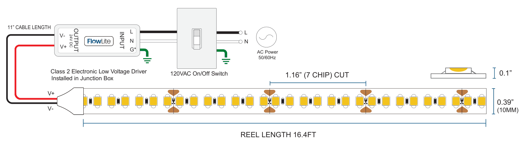
An example system: 120VAC on/off switch, Class 2 low-voltage driver installed in a junction box, 24V DC to the tape. Always review each component’s installation sheet for detailed wiring; diagrams vary with power and dimming requirements (tunable white and RGB+Tunable White runs go through a controller).
Channels
- Plaster-in / trimless: install after the drywall is hung and before taping. Screw the perforated flange to the board face every 8"–12" into framing or blocking, mask the opening, then tape and apply 2–3 coats of joint compound feathered to the profile edge. Install tape and lens only after paint.
- Surface and corner: fix clips at no more than 16" on center, one within 2" of each end, and snap the profile in.
- Recessed: rout the groove to the profile body; the flange covers the cut edge.
- Cut profile and lens with a fine-tooth non-ferrous blade and deburr. Respect each channel’s maximum tape width and wattage. Test before fitting end caps and lens.
Drivers
- Load each driver, or each output, to no more than 80% of its rating: a 96 W driver carries up to 76.8 W.
- Outputs of 96 W and below are Class 2. Never connect outputs in parallel; feed each run from its own output.
- Use one dimming method: a compatible phase dimmer on the line side, or Class 2 0–10V wiring (violet +, gray −).
- Mount drivers in a dry, accessible, ventilated location, never in insulation.
24V voltage drop & wire length chart
Maximum distance from the driver to the beginning of the tape at a 3% drop (23.28V), by wire gauge and total load. These are general guidelines for choosing wire gauge.
| Wire gauge | 10 W .42 A | 20 W .83 A | 30 W 1.3 A | 40 W 1.7 A | 50 W 2.1 A | 60 W 2.5 A | 70 W 2.9 A | 80 W 3.3 A | 90 W 3.75 A | 100 W 4.2 A |
|---|---|---|---|---|---|---|---|---|---|---|
| 20 AWG | 85 ft | 43 ft | 27 ft | 21 ft | 17 ft | 14 ft | 12 ft | 11 ft | 9 ft | 8 ft |
| 18 AWG | 134 ft | 68 ft | 45 ft | 33 ft | 27 ft | 22 ft | 19 ft | 17 ft | 15 ft | 14 ft |
| 16 AWG | 215 ft | 109 ft | 72 ft | 54 ft | 43 ft | 36 ft | 31 ft | 27 ft | 24 ft | 22 ft |
| 14 AWG | 345 ft | 174 ft | 115 ft | 86 ft | 69 ft | 57 ft | 49 ft | 43 ft | 39 ft | 36 ft |
| 12 AWG | 539 ft | 272 ft | 181 ft | 135 ft | 108 ft | 90 ft | 77 ft | 68 ft | 61 ft | 56 ft |
| 10 AWG | 784 ft | 397 ft | 263 ft | 197 ft | 158 ft | 131 ft | 112 ft | 98 ft | 97 ft | 82 ft |
Troubleshooting
Tape light does not light up
- Make sure the DC power supply is on and receiving power.
- Confirm correct polarity (+ to + and − to −) at every joint and at the 24V DC power supply.
- Check all connections, including any switch or dimmer between the power supply and the tape.
- Test with a multimeter to confirm the tape is receiving 24V DC.
Only part of the tape light is lit
- Check the connections to the unlit section, and the polarity at each joint.
- If only one LED series is out, cut out the damaged group and splice the tape back together, or replace that section.
Tape lights blink on, then go off
- The power supply is not adequate for the length of tape. Install a higher wattage supply (loaded to 80% or less) or shorten the run.
LEDs farthest from the power supply are dimmer
- This is voltage drop. Shorten the 24V DC feed wires or use heavier gauge wire between the power supply and the tape (see the chart below).
- Check that the run does not exceed the product’s maximum run.