Every conductor has resistance, and resistance turns some of the driver's voltage into heat before it reaches the LEDs. In tape light that loss shows up where you least want it: the far end of a run that is visibly dimmer, or slightly off-color, compared to the start. Planning for voltage drop is how a 40-foot cove ends up looking like one continuous line instead of a gradient.
Two places voltage is lost
In the home run. The wire between the driver and the first inch of tape carries the full current of the run. The longer that wire and the thinner its gauge, the more voltage is lost before the light even starts.
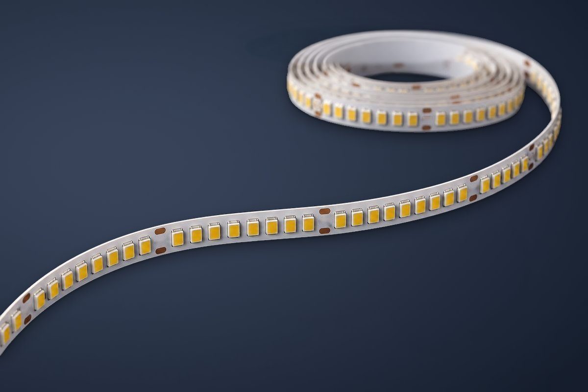
Along the tape itself. The copper traces in the tape's circuit board also have resistance. Current is highest at the feed end and tapers along the run, so the far end sees the lowest voltage. This is why every tape has a maximum run length: 16.4 ft per feed for standard FlowLite tape, and up to 49.2 ft for constant-current long-run tape.
Reading a 24V wire chart
The chart below gives the longest wire distance from the driver to the start of the tape that keeps the drop at or under 3% (24V down to 23.28V). Find your total load across the top, then read down to a gauge that covers your distance.
| Wire gauge | 10 W .42 A | 20 W .83 A | 30 W 1.3 A | 40 W 1.7 A | 50 W 2.1 A | 60 W 2.5 A | 70 W 2.9 A | 80 W 3.3 A | 90 W 3.75 A | 100 W 4.2 A |
|---|---|---|---|---|---|---|---|---|---|---|
| 20 AWG | 85 ft | 43 ft | 27 ft | 21 ft | 17 ft | 14 ft | 12 ft | 11 ft | 9 ft | 8 ft |
| 18 AWG | 134 ft | 68 ft | 45 ft | 33 ft | 27 ft | 22 ft | 19 ft | 17 ft | 15 ft | 14 ft |
| 16 AWG | 215 ft | 109 ft | 72 ft | 54 ft | 43 ft | 36 ft | 31 ft | 27 ft | 24 ft | 22 ft |
| 14 AWG | 345 ft | 174 ft | 115 ft | 86 ft | 69 ft | 57 ft | 49 ft | 43 ft | 39 ft | 36 ft |
| 12 AWG | 539 ft | 272 ft | 181 ft | 135 ft | 108 ft | 90 ft | 77 ft | 68 ft | 61 ft | 56 ft |
| 10 AWG | 784 ft | 397 ft | 263 ft | 197 ft | 158 ft | 131 ft | 112 ft | 98 ft | 97 ft | 82 ft |
24V voltage drop & wire length chart, 3% drop (23.28V). Maximum distance from the driver to the beginning of the tape, by wire gauge and total load. Every FlowLite tape spec sheet carries the same chart for its own wattage.
A worked example
A lobby cove needs a 16.4 ft run of 4.4 W/ft tape, and the driver sits in a closet 35 ft away.
Calculate the load
16.4 ft × 4.4 W/ft = 72.2 W, about 3.0 A at 24V.
Round up to the next column
72.2 W falls between the 70 W and 80 W columns. Always use the higher one: 80 W.
Read down to your distance
In the 80 W column, 18 AWG reaches 17 ft and 16 AWG reaches 27 ft, so both fall short. 14 AWG reaches 43 ft, which covers 35 ft. Specify 14 AWG.
Shorten the run and the numbers ease quickly. A 10 ft run is 44 W, which uses the 50 W column, where 16 AWG reaches 43 ft. Our voltage drop calculator does this lookup for you.
Strategies for long lines
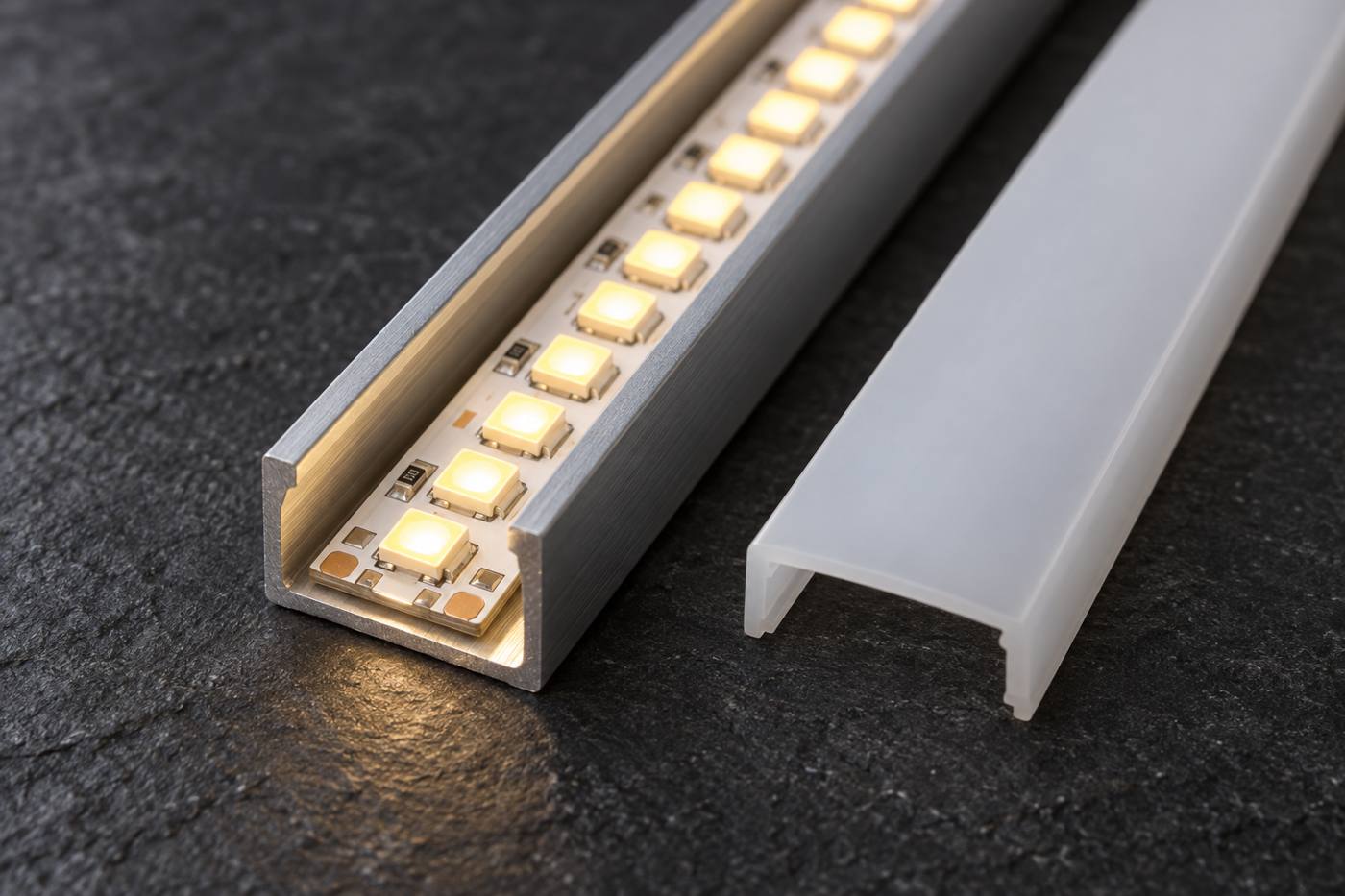
- Split into segments. Break a long line into runs of 16.4 ft or less and feed each one separately. Cut points every 1.16" make it easy to land segment joints in a channel without gaps.
- Move the driver closer. A remote driver location is often the single biggest cause of voltage drop. Locating drivers in accessible junction boxes near the runs keeps the home runs short.
- Upsize the wire. Going up two gauges roughly doubles the allowable distance.
- Feed from the middle. For a symmetrical line, a center feed with two runs heading in opposite directions halves the distance each run carries current.
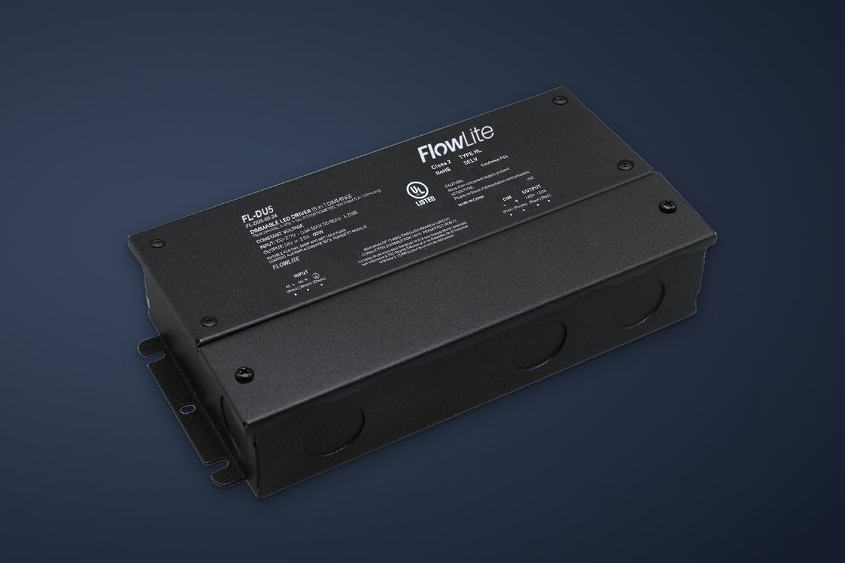
- Use multiple drivers. Distributing load across several drivers shortens home runs and keeps each one inside Class 2 limits.
Key takeaways
- Voltage is lost in the home-run wire and along the tape's own circuit board.
- Standard tape: maximum 16.4 ft per run, each run fed separately. Long-run tape: up to 49.2 ft.
- Use the next higher load column in the chart, then pick a gauge that covers the distance.
- Short home runs and sensible feed points matter more than anything else.